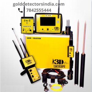
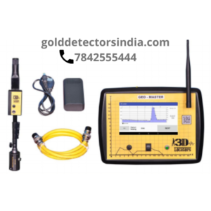
Geo-Master
LPS 1200 system
Description
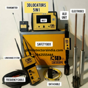
Geo- Master is a powerful Water Detector build with advanced instrumentation in groundwater exploration with five technologies composed in one system/device. It is equipped with Long-range positioning system, geomagnetic sensing system, transmission system, very low frequency detecting system, geo-frequency detecting system. Technologies are relevantly matched depending on the subsurface geological conditions.
Features
Geo-Master water detector is designed with the following five Technologies
1. Long-Range Positioning System
2. Geomagnetic Sensing System
3. Geo-Frequency Sensing System
4. Very Low Frequency Detection
5. Transmission Technology
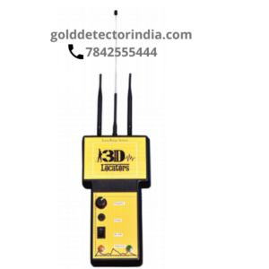
Long-Range Positioning System
Long-Range Positioning system is a locating system designed to locate a fault-zone based on Magneto Impedance technology with live data generation to evaluate a fault zone and its strength. 3D locators developed the first long range positioning system with most advanced features.
Geomagnetic Sensing System
The geomagnetic survey is an efficient method for modeling of geological structures as well as for non-destructive detection of near-surface anomalies of human origin.
Geo-Frequency Sensing System
Dielectric permittivity (0) The ‘absolute’ permittivity of a dielectric, being the ratio of the electric displacement to the electric field strength at the same point. Its value for free space is 8.854185 x 10⁻¹² F/m.
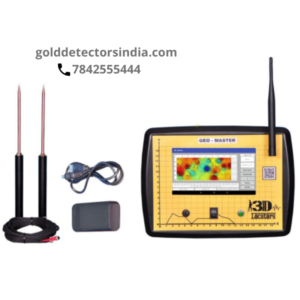
VLF Sytem
Very Low Frequency Detection
Very low frequency detection technique works on magneto telluric technique developed in the subsurface penetration. The technology can study the subsurface layers and interpret on contour mapping.
Transmission Technology
Data transmission refers to the process of transferring data between two or more digital devices. Data is transmitted from one device to another in analog or digital format. Basically, data transmission enabled devices or components within devices to speak to each other.
Geo-Master Specifications
System Specifications
Technology : Magneto Impedance (MI)
Front Range : Min 100M – Max 2000M
Depth Range : Min 100M – Max 500M
Battery : Li-ion Rechargeable
Transmitting Antennas : Long range wireless coverage, Antenna is heavy-duty, weather proof Antenna for extending the range of your 802.11a/b/g/n/ac
Receiving Antennas : SMA-Female; Band: UHF ; Frequency: 400/470MHz ; Input Impedence:50ohm
System Holder: Gyroscopic system holder with non-conductive material for noise reduction.
Charger: 5V 1 A DC charger
Indication: Buzzer
Charge indication: LED
Wireless communication: Bluetooth
Frequency range selector: POT
Reporting: Digital
Report Sharing: E-mail
Gain selection: 1X – 10X
Location and depth Axis: 0-3000
SI Unit: Nano Tesla
Input: Manual
Coordinating system: GPS
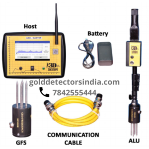
Parts & Features
Long Range Positioning System
• Built-in Processor
• Sensor Modules
• Inbuilt rechargeable batteries and signal
• Receiving system
Trans-receiver Antennas
• Long-range wireless coverage
• Weather-proof antenna for extending the range of your 802.11a/b/g/n/ac
• The amplified signals are received via the receiver antenna
System Holder
• System holder is designed with non-conductive materials to avoid magnetic interference.
• Inbuilt bearing drives the system
Charger
• Input Voltage (V) 100-280VAC
• Input Current (mA) 100
• Output Power 5V 1A
• Load Regulation (%) +/- 5
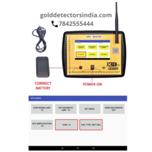
Host System
• Host system powered on Android platform works as a host to run the software for LPS.
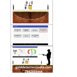
Working Methodology
1. The Telescopic antenna is the receiver antenna and the DBI antennas are the transmitter antenna. Connect both the antenna to the long-range system as shown in the picture below
2. Connect the system holder to the base of long-range system, by rotating the thread attaching the base connector, and ensure it is fit properly for gyroscopic positioning.
3. Turn ON the LPS-1200 system and the Host System to build a connection for data transfer. Once the beep sound is heard that indicates the system is ON and waiting for Tab receiver.
4. In the Host System homepage, select the long range survey, where the system prompts to the next step of range selection and tablet communication. Enter the Password 1234.
5. Select the appropriate front-range and depth-range depending upon the areas of topography and geological conditions. After selection, click on the communication address shown in the tablet to build connection in between the Tab and Long-range system.
6. Once the system is connected and both host and long-range system is paired we start receiving the live data on the screen indicated as a graphical dial. It also shows the frequency at the bottom left of the tablet screen. For the first time, system may ask for authentication and the password is 1234.
7. Adjust the frequency to the low frequency signals and follow the readings shown on the display according to the movement of the long-range system.
8. Start from any corner of the property depending on the topography of the land and physically hold the long-range system ad rotate in clock-wise or anti clock-wise until we get the highest data on the display dial. The highest data indicates we are on the highest magnetic axis to start the survey.
9. From the highest axis start the survey and follow the direction and continue the survey until the long-range system swivels 180o which indicates that we are crossing the target.
10. Mark the target and confirm the directional fluctuation at a distance of 5 meters by checking teh system pointing direction from four sides of the target. After ensuring the number of directions , increase the frequency to a medium or higher frequency to check the short-range. Fold the telescopic antenna to check the pin point target.
11. From the highest axis start moving towards the target to which ensures the rotation in clockwise or anticlockwise to confirm that we are on the target.
12. The rotation of the system confirms that we have pointed a fault zone, mark the confirmed target. Next step is to conduct a depth survey to calculate the depth from the surface to the subsurface fault.
13. Extend the receiver antenna and decrease the frequency to low frequency to conduct the depth survey. We need to follow the data on the depth axis screen which is the y-axis for the location axis.
14. From the located target follow the highest axis to ensure we get 180o in the long-range system which shows there is a magnetic difference on the y-axis of the location. Mark the specific location where we get the difference and continue the survey on the same axis to check for the second and third difference area.
15. Measure the distance from the target to the differed zone on the depth axis followed by distance to the first difference, second and third , measure the distance in meters.
16. Make a note of the measurements taken and finish the survey for further verification by the next cross checking method.
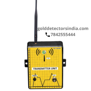
Transmitter
Transmitter Working
TRANSMITTER
Data Transmission refers to the process of transferring data between two or more digital devices. Data is transmitted from one device to another in analog or digital format.
Basically, data transmission enables devices or components within devices to speak to each other. The pass band modulation and corresponding demodulation (also known as detection) is carried out by modem equipment.
The transmitter helps in boosting the signals in locations where the land is in areas filled with disturbing materials ferrous materials). The signal helps in boosting the data received by the long-range system.
In areas where communication channels get disturbed it is recommended to use the transmitter system for accurate positioning.
WORKING
1. Fix the transmitter with the M,N electrodes at a distance of 10 meters in the ground , where the signals are getting disturbed.
2. In the settings, click “wireless sensor on”.
3. Now start the long range system which gives the transmission logo, which helps in continuous data communication.
VLF System
VLF Connection System
VLF (Very Low Frequency ) System
VLF defined as very low frequency sounding measures the subsurface via the electrodes placed at a fixed distance. VLF electromagnetic technology is used to examine the geo-environmental problems in shallow, low conductivity sedimentary layers, in groundwater exploration and in locating the position of anomalous source bodies beneath the surface.
MT method is a passive electromagnetic (EM) exploration method that measures orthogonal components of the electric and magnetic fields on the earth’s surface. The source field is naturally generated by variations in earth’s magnetic field, which provide a wide and continuous spectrum of EM field waves. These fields induce currents into the earth, which are measured at the surface and contain information about subsurface resistivity structures.
Connection Procedure
• Turn on the Host system and click on VLF survey settings, set up to the required amplification.
(picture)
• Connect the probes to the ground at a distance of 10 meters probe 1 at 0 and probe 2 at 10 meters.
• If the ground contact is perfect we get the LED light blinking in the host .
(picture)
Working Methodology
1. Click on the VLF survey after connecting the cable and probes to the system.
2. Fix the probe 1(M) at point 0 meters and probe 2 (N) at 10 meters.
3. Check if the LED in the host system flickers which indicates the ground connection is connected.
4. Click on profile to open the curve graph page in the host system.
5. Click process to record the frequencies from the ground which collects the continuous data from surface to subsurface.
6. On completion of the data collection move the probes from 0mts to 1mts (M probe) and from 10mts to 11mts (N) probe followed by 1-2………., 11-12…….and record the complete line.
7. In the curve graph we can see the increase and decrease in the data collected at each point and the most value decreased station is selected as the considerable point of drilling.
8. Click profile to check the 2D structure of the survey and the imaging gives a fair idea in graphical representation on subsurface structure to understand the depth for the station which is selected.
Geo-Frequency System
Geo-Frequency System
Geo-frequency system is a unique invention in the field of groundwater exploration to analyze the permeability of the site by prospecting the closer sectional variations by dielectric permittivity technology parameters.
The Geo-frequency system is a useful equipment in the geological and hydro geological study designed to explore the subsurface permeable factor and estimate if the site is feasible for water well drilling, Geo-frequency surveys can map the depth of the aquifer system, rock strength of a particular station, permeability, quality, salinity, quantum and station coordinate.
Geo-Magnetic System
Geo-Magnetic Sensing System
Geomagnetic surveys are carried out where areas are non-dimensional and are small to conduct other surveys like long-range or VLF surveys as they require a min of 20mts linear space.
Geomagnetic survey is briefed as a non-contact survey. In which we calculate the geomagnetic variations for every meter manually. Magnetic surveys can cover layout in a linear direction by visualizing the field difference in positioning a fault zone.
Co-partners: https://sniperelectronics.in
People who viewed Geo-Master also viewed LPS-1200.